Tuesday 2 February 2016

Bad Motivators, the smoky bit

After having so much fun with JamesF's R5, i had fallen in love with the blowing motivator and especially the smoke. :D

So having built an R5 and R4 dome, that dont have all the flappy panels, they needed more life. :)  I will do a blog update for each dome when complete.  But thought someone might benefit from our findings with vapes for bad motivators.

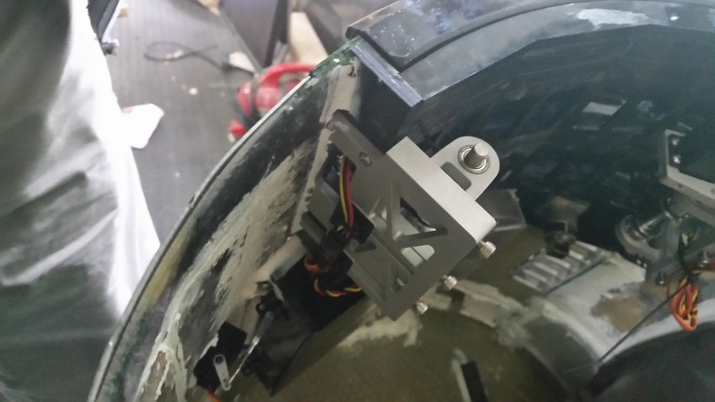
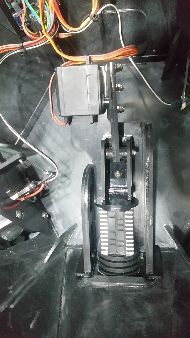
I started by making motivators and lifters for R4 and R5.  The lifter is a liner slide and a servo, simple but effective, and solid enough for this role.  As long as the motivators arent too heavy they will work well, im only testing them at 5v, but on R4 i will run the servo at 6v, so should be a little quicker.


After consulting with James Short, we decided to go for a sub ohm vape solution, and to be able to tweak it for best effect we needed a proper vaping solution.  James had a mod box pcb and a few other bits, so i bought a small 12v pump, some hose and a few tanks and adaptors.

When we got all the bits together, we found we were short of buttons and screen, and most importantly a suitable battery.  So for testing we rigged our chosen tank and the pump but used an off the shelf vaping box for the power and control.

The pump isnt very powerful, but is great for our needs, and by keeping hoses short the pressure needed is low. :)  This will be controlled via a relay connecting it directly to 12v, and will be timed to suit the look.

The trigger will also be fired using a relay, in place of the button.  Looks like about 5s of firing will be perfect, maybe with a couple of seconds extra blow to clear out the system.

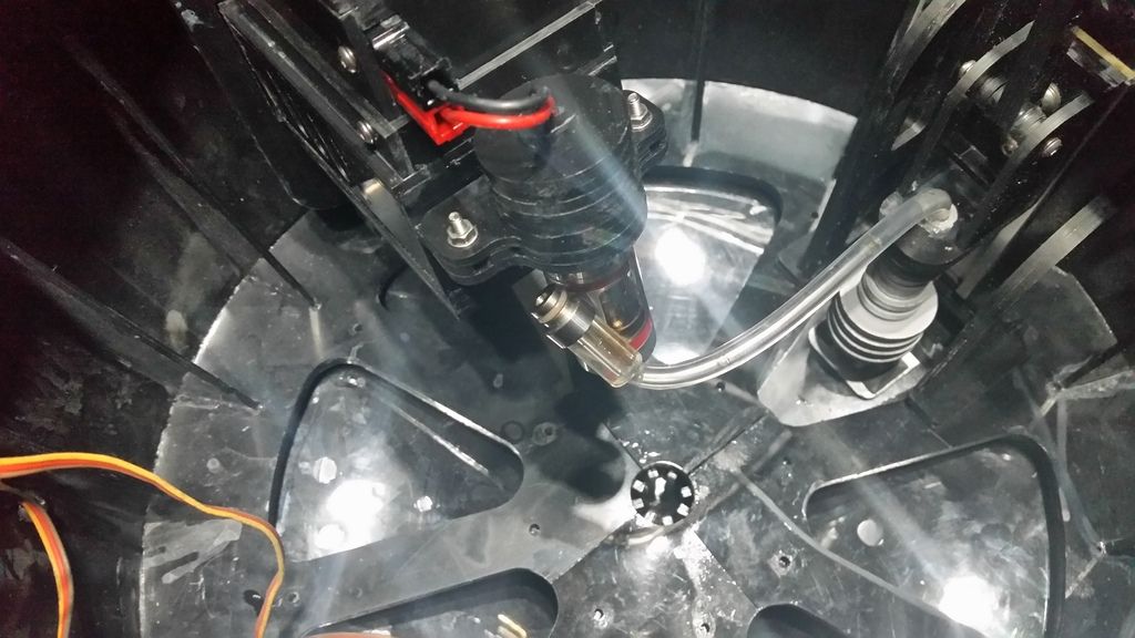
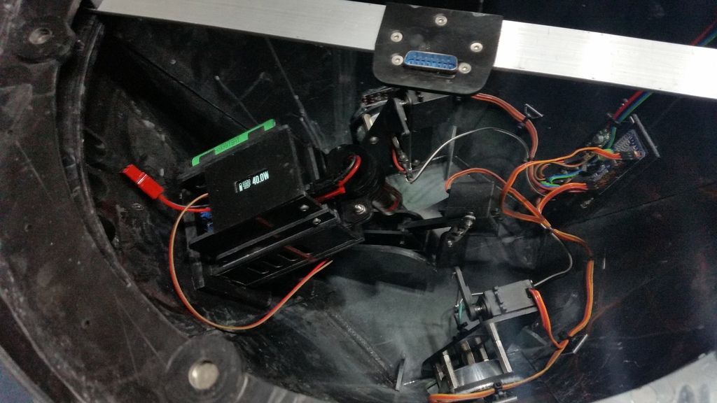
So all mocked up, we connected it to R5's motivator and lifter and gave it a proper test and tweak.  The results were great, might have to turn it down. :D


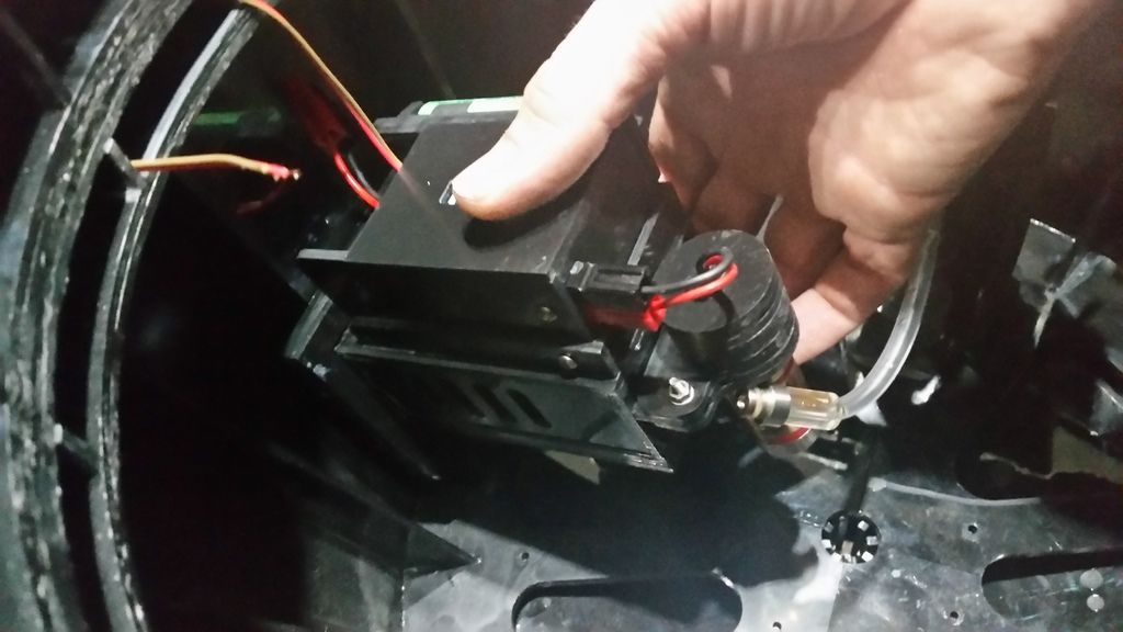
I then cut the housings, the pump is mounted in a box with the hose connecting via a small section of heat shrink directly into the tank vent, and the relays for the pump and trigger control are mounted to that.  The tank and wiring are removable, for easy filling and service,  And the mod box and battery mount to the tank box but can be removed for testing and setup.

For this version i havent added buttons, once setup it should just run.  Will find out of i need them, if i do i will redo the modbox.

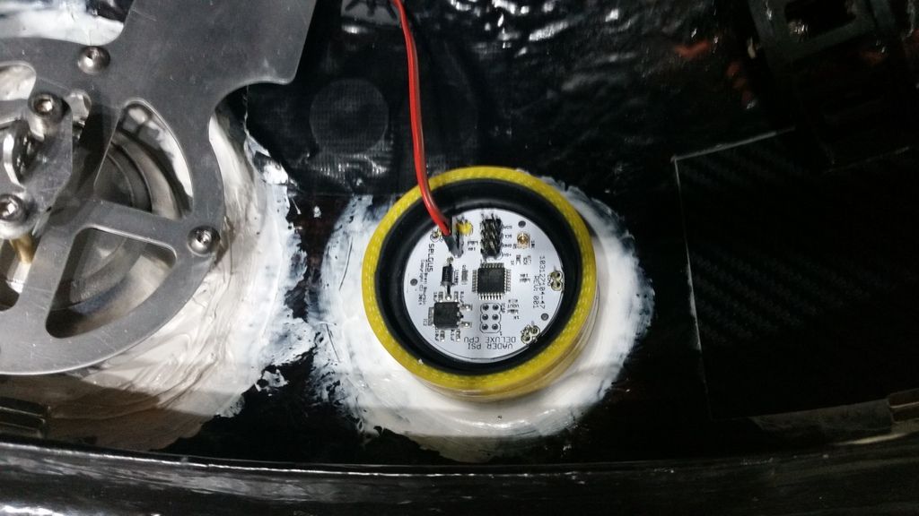
In order to be able to mount this in several domes, i added steel discs .8mm below the surface, and magnets to the mount, the box then slides onto the mount and clicks in.


R5 mount:

The shopping list isnt pretty reading tho.

Battery 18650   £6.50
Battery holder    £2 (already had, cheers James)
DNA 40D PCB and Screen    £42 (already had, cheers James, but needed £11 replacement screen)
USB charge board         £6  (already had, cheers James)
Subtank Mini Mk1          £20  (already had, cheers James)
Tank power mount          £1
12v Pump                       £1.39
5v relay dual board    £5  (already had)
6mm OD 3mm OD Hose  £3

Plus fluid. :(  So not cheap at £90+ but awesome, and actually only cost me like £30 for this setup. :D  And not a massive investment compared to the cost of a droid.

If this works well and doesn't drip, I may rig up another special one for BHD eventually. :)

But thinking about dripping, i thing the condensation may collect and drip back through to the pump, ideally a collector tank in-line would solve that, maybe an upgrade.  But will most likely run the pump for a bit after smoke to try and cool and clear the system,

Wiring is done on R4, R5 needs a little more, Some scripting and more testing and i will post an update for each dome. :D


Monday 12 October 2015

More Tweaking

X2 and i took a tour of the village.  Still problems to solve, but so much better. :D


After the jaunt, i decided that i needed to simplify a few things, just to make life a little easier.  I got the right failsafe applied to the 2x32 Sabertooth, so i could remove the relays for the feet.  He cant be pushed now without the battery, but saves any current worries there.

I also reduced the max current to 32A per motor from 64A, but i have already had another trip, that was in special circumstances but i think i might be hitting the 30A constant limit, rather than the 90A peak, so i will try and half the current again, to 16A per motor and see if the ESC protects the battery limits that way. :)

After removing the feet relays, i decided to increase airflow on the box, so got the Dremel out and cut lots of holes. :)  The ESCs should be able to breathe a lot easier now.

The speaker connectors were getting lose, so i added some RCA connectors to the box, and run the speakers through those.  At only about 25W RMS it should be fine. :D  Still sounds ok. :)  The DC converter for the amp had failed, and was the cause of some of the tripping, so that has gone, the amp will have to do running directly at the battery voltage.

Then i decided to look at the PWM controller setup, the way i have been bypassing the power rails has caused a few issues, so i wanted to use code to turn the servos off.  Eventually the code for the body was working well, a little rough, but no relays and better than it was before the change.  So i rewired dome, applied the change in the same way.  Powered it up, but all the servo spots were different!  And 2 of the cheap HP servos were already dead (they had been buzzing hard and i hadnt sorted it). So about an hour later i had all in and the spots and it was still horrible!  It did work but there was still a lot of Buzz, so i added timers for all the servos, now they power off just after they finish travel. :)  Even the HPs are unpowered if not moving.  Works great now, and the wiring is child's play.

While in there playing i edited the way the HPs move in random mode.  Previously, they picked one of 5 points, one of the 3 HPs, then flashed and moved it.  But this always resulted in the max speed of the servo and only a single movement.  I wanted more life in it.  After a little thought, i found a clever little trick.  The Slow Servo library uses the start and end and time for the travel.  But it doesnt know the start, so you have to give it that value.  So by picking one of the 5 spots for the start and one of the 5 for the finish, the servo has to jump onto that path and then will move at the speed depending on travel distance because the time for the motion is set to the same for all random HP moves.  So the original code was only changed by one random and 2 lines, but the effect is so different. :)


Next up i need to get the Vegas kit done for X2.  But i might go back to BHD and apply the Diamond drive, de-buffered PS2 pad code and the servo relay removals. 

Sunday 27 September 2015

Drive challenges and tweaks

X2 is now all wired up and working.  But here is where the fun began. :D

I had a funny noise coming from the drive.  It haddn't happened during testing.  But i had bought a 2x32 Sabetertooth to run it, and eventually i found it was the ESC settings, limiting the current.  So that seemed to solve it.  But no, after a few mins running the problem would return.  It didn't take long to work out the problems, but i had already started down a side mission.

The mix from the stick to the motor speeds on BHD has always been my way,  Basically, adding and removing the X value from centre, from the Y value from centre.  This had a few key points.
1.  Turning was able to be factored so that drive and turn felt very different.
2.  At max foot speed on one motor you cant add to it, so max range driving differs to in range.

So after a little researching and a lot of simple maths it all came down to a few lines. This was the inspiration, and the base for hte method:
http://www.rchordata.com/files/Using%20Diamond%20Coordinates%20to%20Power%20a%20Differential%20Drive.pdf

This one has the following:
1.  Turn and drive are equal, so full spin is full forward and full back on the motors.
2.  This map is true in that it adjusts both motors for better control, especially at top end.

Map stick input to easy grid -100 to 100 in both axis, including deadzones.
Then constrain the coordinates into a diamond shape.  Using 2 line equations using coordinate geometry to find the intersect, boiled down to the minimum equation.
So if (YDist>(XDist+100)) {  //  if outside top left.  equation of line is y=x+100, so if y > x+100 then it is above line.
OK, the first fun bit. :)  so for the 2 lines this is always true y = m1*x + b1 and y = m2*x - b2
y - y = m1*x + b1  - m2*x - b2  or 0 = (m1 - m2)*x + b1 - b2
We have y = x+100 and y = ((change in y)/Change in x))x
So:   x = -100/(1-(change in y)/Change in x)) and using y = x+100 we can find y with the new x
or:
            XDist = -100/(1-(YDist/XDist));
            YDist = XDist+100;
          } else if (YDist>(100-XDist)) {  //  if outside top right
            // repeat intesection for y = 100 - x
            XDist = -100/(-1-(YDist/XDist));
            YDist = -XDist+100;
          } else if (YDist<(-XDist-100)) {  //  if outside bottom left
            // repeat intesection for y = -x - 100
            XDist = 100/(-1-(YDist/XDist));
            YDist = -XDist-100;
          } else if (YDist<(XDist-100)) {  //  if outside bottom right
            // repeat intesection for y = x - 100
            XDist = 100/(1-(YDist/XDist));
            YDist = XDist-100;
          }
So all coordinates are now in the diamond.
Then we need to map a diagonal 100x100 grid onto the diamond and find the motor speeds.
For the left motor, send ray to y = x + 100 from coordinates along y = -x + b
Find for b, solve for coordinates and resut in y then scale using y = (y - max/2)*2
          int LeftSpeed = ((XDist+YDist-100)/2)+100;
          LeftSpeed = (LeftSpeed-50)*2;
For right send ray to y = -x + Max from coordinates along y = x + b find intersction coordinates and then use the Y vaule and scale.
          int RightSpeed = ((YDist-XDist-100)/2)+100;
          RightSpeed = (RightSpeed-50)*2;
This results in a -100 to 100 range of speeds, so map to usable range.
          LeftSpeed = (map(LeftSpeed, -100, 100, FootMaxReverse, FootMaxForward));
          RightSpeed = (map(RightSpeed, -100, 100, FootMaxReverse, FootMaxForward));

Easy and a completely new mix. :D  Works great, and feels a lot more controllable, especially with the rework on the PS2 buffering issues.  The mix is great.

But that wasnt what i wanted.  I was going to look for a way of driving forwards or backwards on both motors only.  But hey ho. :D  Will try again.

Chis James was in the UK so popped in.  He spotted the supply lead was getting warm, so we upgraded that and it was like a different droid. :D  But then started throwing tracks. :(  And popping wheelies as soon as we added the dome.

The wheelies were a balance and shocks issue.  The suspension is too soft in front when fully loaded, so it is stored energy into the wheelie.  So i decided, for now, to cover the shaft of the damper with rubber washers, so there is some give, but not as much and can run loaded.  Also i looked at the setup and the front height has crept up with the changes, so that was about 15mm too high, so lowered the ride and the adjusted spring and it was a lot better, but still had a tenancy to pop.  So i added about a kilo of Lead to the front of the foot and it seems much more stable.

The shock shoulders rubber bushes have worn already and the holes are now sloppy, they were the uber soft ones, so the 72A are out, and 89A are next. :D  On order. :)  That will help with the rigidity and the wheelies too.

Eventually i spotted it was always the same track when it threw one.  So James and i striped them, got the adjuster moving and set them up properly.  The difference was brilliant.  He now skips over the grass rather than the tracks gripping and twisting, they turn with the feet a lot more than dragging.

I am going to redo the centre, the caster has a lot of slop in the bearing and the noise is pants.

So after a lot more playing, i now have him driving pretty well, and under better control than BHD. :)  The fast and slow modes are setup for in and outdoor use and should work well. :)  I eventually went with the ramping via BHD and a linear map on the drive.  That gave me the best adjustable control via the pad.  But i now have all the failsafes, voltage levels and battery types etc set on the Sabertooth.

The mancave is the ultimate droid tight spaces challenge,  :D   He is now easy to drive even in the tight walkway past the bench, where there is only about 5" clearance total.  I couldn't even get him lined up for it at first. :)

Saturday 20 June 2015

Dome lights and more body work

Steady progress still.

I have wired up and neatened all the 12v sources in the dome and as much of the servo leads as i can.  But to be able to continue on the dome I'm now waiting for servos that should be here by now. :(  I have had him on for the last few nights.  Really pleased with the colour choices.


I have Seglus's Vegas PSI (Mk1) and JoyMonkey's R-Series logics (Mk1).  I didnt fancy having to write code for these, so i decided to use the Rear PSI on the front and the front on the rear, in R2-D2 colours.  With that choice made James and i had a play with the R-Series colours to get something that looked right.

Fronts have a Green/Orange fade with white spots.  To try and mirror the Green/Orange PSI.  Not a great vid, LEDs dont like being filmed. :(


Then the rears are Blue/Purple and Red.


I think it suits him.  The lights are off, or not installed on the screenshots, so i figure this gives us free reign.

The diffusion on the PSI is a trial and error thing i did a while back.  It is a 1mm layer of plastic from a Hobbytronics delivery box, then OHP inkjet film with the honeycomb print, then 10mm (2 x 5mm) light box perspex. Boards sit on the back, spaced off  with, and held in to the silicone hose (my PSI holders) by large O rings, smaller diameter between pcb and perspex and thicker to retain it. Looks great in person, but tricky to film.


I then mounted the servo for the big door.  Using a modified version of the same servo holders i had used in the dome.

After that i finished wiring up the UAC servos to a communal point.  And glued it in place using HP40.  Seems nice and solid, and thanks to a little shaping and the pull of the glue it all lines up well.  A touch up of the paint and it looks like it was always there. :)


CBI door servo and PCB next.  Then id like to look at the front foot one more time before testing.  I don think the positions are optimal at the moment.  Maybe time to start modelling that in Cubify.


Saturday 13 June 2015

Utility Arm Carrier and Arms

The Master setup has already failed.  The dremel shaft eventually failed at too low force. :(  But only in the anticlockwise direction. :(  So I have ordered a alternative to try.  I also found that i can use a bearing in the arm, that may help too. :)

I had built the UAC to replicate the JAG V5 UAC points that i needed, but from CNC cut styrene.  It took a few goes to get right. I glued the carrier up with the arms installed without spacers, but due to the amount of slop the first 2 attempts were binned, so i replaced the bearings, and used a nice flange bearing instead.  

These are a few pics of my final prototype:


I then redid in black and added an LDP / Vegas lights strip carrier. So all glued up and skins added.  I removed the arms and painted.

The complete reassembly was a pain.  Having to thin the spacers to the right heights, have all elements aligned to be able to do up the all the grub screws, and insert the spacers, and the belts, and the servo, all inserted in the right order, the right way up.  So all in, but scratched all over. :(  And not clearing nicely, and rather strangely, sitting differently, so a little filling later they were opening and closing pretty well, paint was touched in, and all working well.  Good enough for this job. :)


And the Vegas lights should be better concealed on X2 :D


This is probably easier on an Ali frame, but without being able to strip the UAC the install was very tricky and tight.  Now it is installed, the Arms open beautifully and the mechanics of the mech are superb. 


I spotted i had missed the front power coupler.  So masked and painted that too.  So the whole droid is now externally done. :)  


James is working on the dome motor hub for the A&A gear and the pitman i mounted in the top ring.  I hope he will update you on that when complete. :)

Not too much more to go. :D

Monday 8 June 2015

Master Utility Arms

These have been bugging me for a while.  I ordered the Servo City shaft adaptors and they took nearly a month to come.  I had already bought the recommended HS-65MG servos so finally once i had the dome done, i could crack on.

I had broken one of the Dremel hand shafts not long ago.  So i got the new one running and cut up the old one.  The centre was just about perfect for the flex shaft in the arm.  So I cut 2 35mm sections and cleaned up the ends.  Then drilled out the brass couplers provided and the servo adaptors to take the 3mm shaft.

The brass bits were great, so easy.  The servo couplers were a nightmare.  The Allen key provided didn't fit the grub screws and the screws didn't fit the adaptor.  So i ended up just gluing the shaft into the adaptor, but the hole is tight and almost threaded, so should hold ok.  But only after a lot of playing.

Grease was needed on everything, it really helped, and also the plastic bush when fully pushed on flared due to the ali of the paw doing so.  So that was trimmed by about 1.5mm in length, with that it rotated quite easily under servo power.  But took a bit of playing to find the right answers.


So with that i painted one arm and sorted the other's mech.  Then painted the 2nd arm. :)

Today i reassembled the painted arm.  The long grub screw for the paw to bush didn't want to go in, so i cut it short and it only grips one side.  It runs beautifully. :) Shame about the wiring colours, i will have to connect these to correct extensions in the body, but it was the only wire of that thickness i had.

2nd one can wait another day. This one is a day older and the clear is still a little soft.


Wednesday 3 June 2015

R2-X2's Dome

We have the Crash dome with the carbon fibre panels.  It is a really nice strong piece, beautifully made.  It is very hard to tell it is a fibreglass dome.

But offering up the standard hinges, the results weren't great.  So we decided to use the CNC and try to make some to suit the thicker dome and the lack of inner layer on the doors.

Starting with the point we wanted the pie door to stop, we designed a new style of hinge, with much greater opening and clearance of the opening.  We then did the same for the lower doors.  After doing the 9 doors, but just hinges, i dropped the dome, busted 3 hinges and proved my dome strength theories and my hinge weak point ones too.  So i redesigned the profile to have holes not grooves, Mk2 is SO much stronger.  I then sorted the servo arm and connection and ran a few tests.


Then i got all 4 pies reinstalled and setup the servos, at that point i couldn't resist another video. :)


So 9 servos, hinges and doors sorted.  But i had a carbon top panel, so it would be rude not to add it as a door too, right?  ;)


James cleaned up and assembled the other 2 HP servo mounts and i cut the top mount to allow the top hinge to clear.  I then test fitted all the logics and any other dome bits.  Once happy i started preparing all the elements and getting ready to paint.

Painting took almost a week.  The carbon panels are a lot of work to get a good finish.  Several filler and primer cycles eventually got them to a pretty good standard.  Then i gave the white bits 4 coats of stain, and the green/black 3-4 of colour and at least 2 thick clear coats. 

The dome stripes was the tricky bit.  I mounted the dome to the Rockler and made a bracket to hold the pencil.  Then slowly rotated the dome marking as i went.  Then using flexible masking tape i masked all the bits to be painted green, filled in the rest with blue masking tape and set to it.

Painting went well, stripes are great, but the blue masking leaked.  So I had to clean quite a bit of the white, but luckily you would have a hard time spotting the fix.  The rear PSI area could be better, but im happy with it, overall it is really crisp and clean.

So here he is, all elements now glued in and ready for the wire up and electronics, :)